A1: Modelling and Laser Cutting
Press Fit Objects
I might have had too much fun with the laser cutter for my press-fit cardboard project. I made a collection of objects using a triangle with three connection points and three different types of connectors with various angles. The angle of the connector determines the geometric form that is created. Triangles have an endless amount of exciting possibilities!
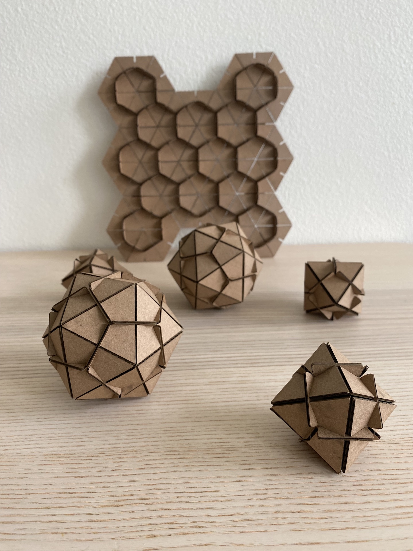
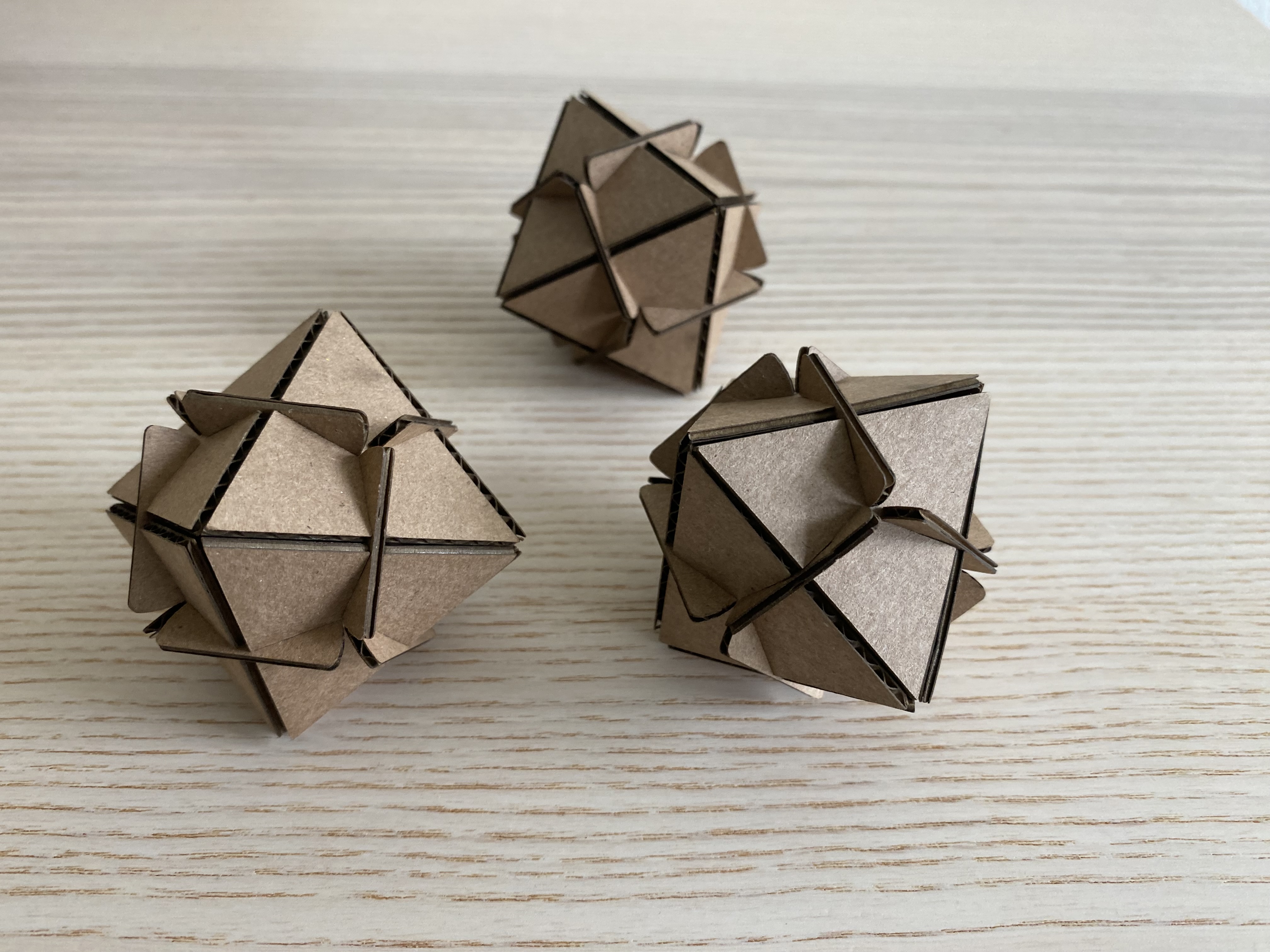
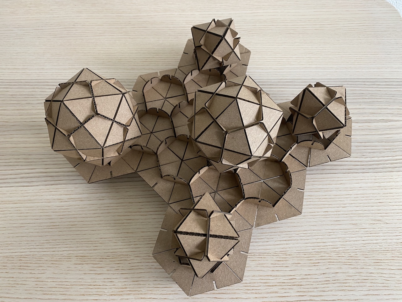
The small geometric form uses 8 triangles and 12 connectors
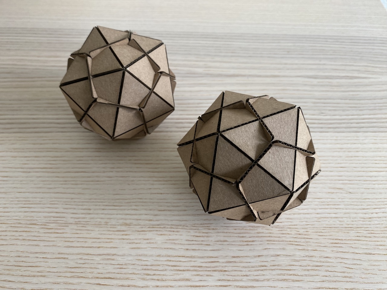
The larger geometric form uses 20 trianges and 30 connectors
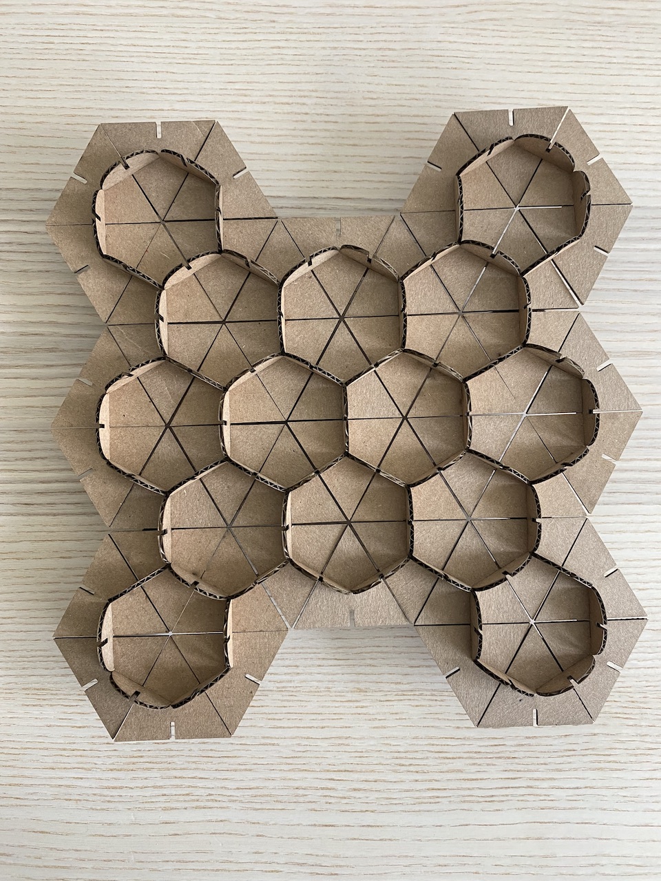
The flat form uses 40 trianges, 61 connectors, and 8 feet
Process
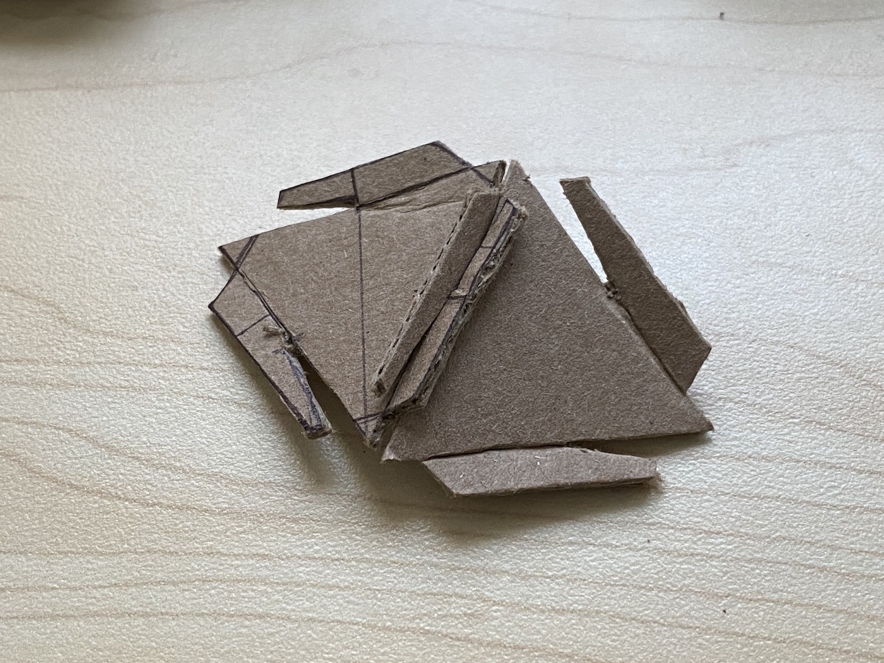
I started by making a paper prototype of the parts for my initial idea: to create a form out of a single piece with slotting joints. Next, I mocked up this initial design in Rhino and did some test laser cuts. I quickly realized that the design was flawed because it relied on scoring and bending the cardboard pieces. From here, I iterated to the two-piece design seen in the final forms.
Early paper prototype
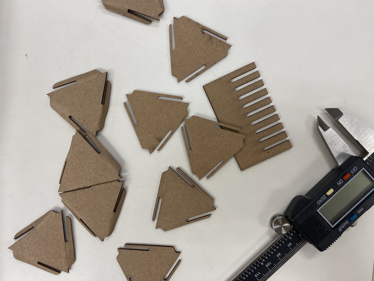
Initial test pieces
Despite using the calipers to measure the thickeness of my mateiral, my first test pieces had a very loose fit. I made a test sheet with different sized slots to find the ideal fit. The thickeness of my cardboared was .067” but I got the best fit when the slots were cut to .054”.
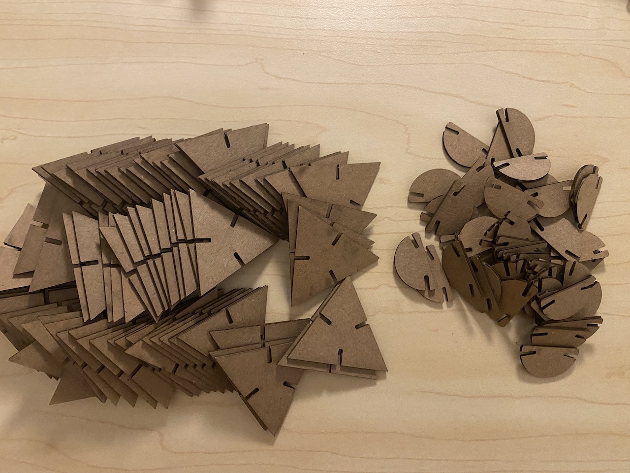
Final Pieces Before Assembly
I laser cut my final pieces on the Universal laser cutter at The 8. I exported the Rhino model to an illustrator file. In Illustrator I adjusted the line weight to .01 pt so that the laser cutter knew to cut instead of etching the pieces. Since I was cutting a thin cardboard, I cut the pieces using the default settings for mat board in the material database of the ULS software. The only adjustment I made was setting the thickness of my material to .067”.
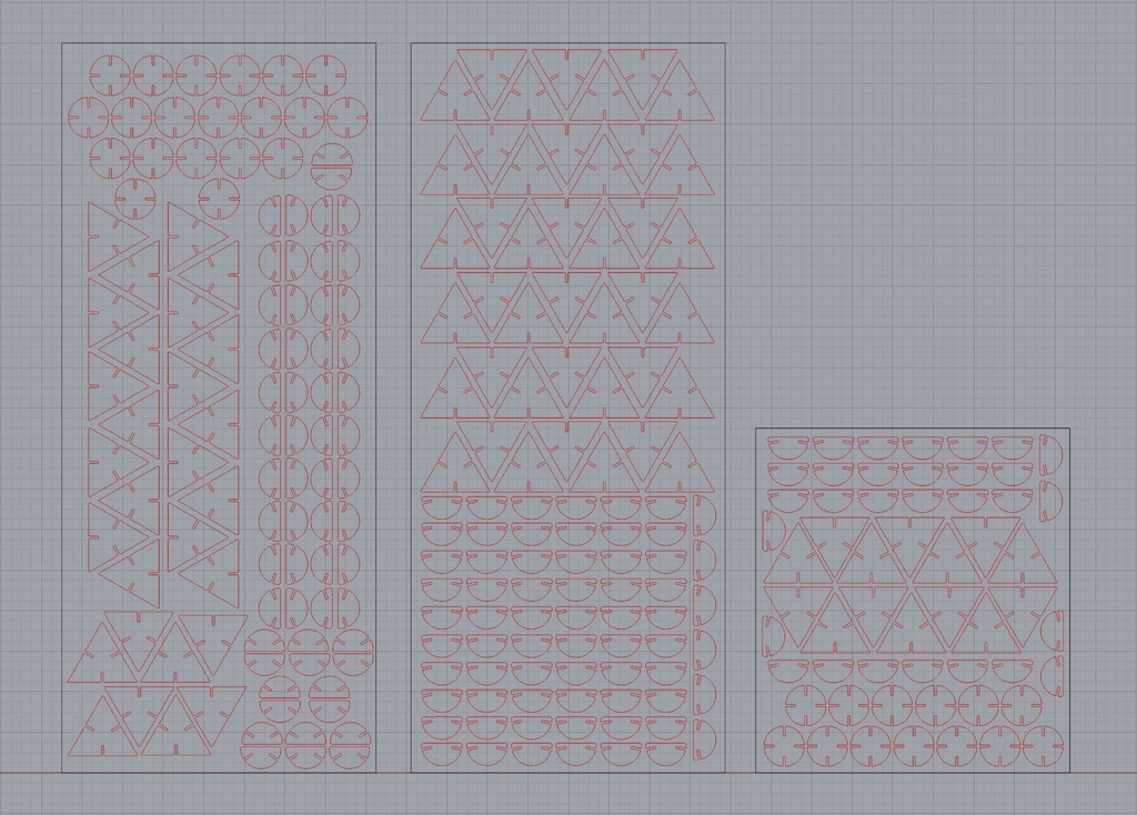
Rhino Layout
The pieces of cardboard I was using were leftover from a prior project. The cardboard sheets were 7.75” x 18”. I tried to optimize how many pieces I could cut on a single sheet of cardboard.